External Accessory Input
This concept refers to the process of capturing the status of switchgear such as indicators, lights, handbrake etc, so that their status can be displayed on SDC. SDC provides the core capability to make this possible, but you will need to create some of the components yourself in order to complete a project with these requirements.
This how-to is not suitable for modern vehicles where the switchgear is connected directly to a CANBus. You need access to electrical signals (such as relay outputs, or lightbulb inputs) for this concept to work. Modern cars that use CANBus switchgear will need an entirely different approach.
If you are trying to capture the output of a sensor such as oil pressure or fuel pressure, then this section is not for you. It only relates to things that can be “on” or “off”.
General Approach
SDC provides a capability to receive CANBus messages for accessory components (any individual item that can be in either an on or off state). You will use this capability to build a 3rd party device that can capture the items you want to integrate and send the right CANBus messages to SDC. You will then build your pageset to recognise the values you are sending using Boolean Gauges.
This is not a small undertaking. You will need experience with electronics and an understanding of how your vehicle’s electrical system works as well as the ability to write software for a microcontroller.
At this point, if you don’t know what CANBus is, then you probably need to do some external reading first. I recommend you do that now so that you understand what the rest of this page is talking about.
The image below demonstrates the system components needed:
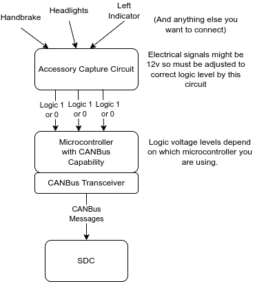
Fistly, you will need to design an electrical circuit that can take the signals from your car’s systems and convert them to voltage levels that are suitable for a microcontroller to read. You will need to research and design this yourself as there are many different possiblities given the large range of vehicles out there. The circuits you produce must also produce the correct voltages so that they can be connected to a microcontroller. Typically these voltages are either 3.3v or 5v for a logic 1 (“on” if you like) depending upon which microcontroller you are using. Your circuit might swap between ground (“on”) and open circuit (“off”). What you actually produce is a design decision for you to make.
You will then use a microcontroller of some sort (such as an ESP32, Arduino, or STM32 or something of that nature), in order to translate the logic level electrical signals your circuit is producing into CANBus messages. These messages will be sent to SDC using the format specified elsewhere on this website.
The following sections describe these steps in more detail.
Can’t I just connect stuff directly to the Pi?
No, you can’t. Apart from the fact that signal voltages will be wrong, the concept of communicating over CANBus to the Pi allows you to logically separate system components so that they don’t adversely affect each other. In other words if you are going to blow something up by connecting the wrong voltage to it, then it’s better to blow up your input circuit than to blow up your Pi and the SDC I/O hat.
In addition to this, SDC does not provide any direct input capabilities at the software level.
Detailed Steps
Build a circuit that can capture the items you need
As previously mentioned, this part is really down to you, as the electronics in cars is varied depending upon the age and manufacturer of the vehicle. In general, you will need to find a voltage or ground source for each item you want to capture. For example, you might choose a switch terminal, a relay terminal, or a light bulb terminal.
The source you choose might be a voltage source (i.e. it might have 12v on it when “on” and be open circuit when “off”), or it might be a ground source (i.e. ground when on and open circuit when off). Or some other combination or different voltages or whatever.
Having found the right source for each item, you will need to build appropriate electronics to convert the source into a microcontroller logic level. What you actually do here is dependent on which microcontroller you are using, but it is recommended that you electrically isolate the input source from the output to the microcontroller circuit. An opto-isolator is a good way of doing this. Isolating like that means that you never connect vehicle level voltages directly to your microcontroller.
Logic levels for a microcontroller are often either 3.3v (for things like ESP32, STM32, or Teensy) or 5v (for Arduino Nano, Mega, Uno, etc). Pins can be driven in different ways; for example they can be pullup or pulldown, meaning that when not connected the pin goes to either logic 1 or logic 0. This can be used to your advantage when designing the part of your circuit that interfaces to the microcontroller. For example, if your logic level circuit output switches between ground and open circuit then you can set your microcontroller pin to an “input pullup”. This would mean a logic 1 is read when the pin is open circuit, and logic 0 is read when ground is applied. In some cases external pullups or pulldowns may be required - it depends on the microcontroller and the circuits you have built.
For each accessory source you will need to select a pin on your microcontroller and connect your logic level circuit output to that pin. The software that you will write will read that pin and know that the pin relates to a specific accessory.
Configure a microcontroller with CANBus support
Some microcontrollers come with what is usually referred to as a “CANBus Peripheral” on board. STM32, Teensy, and ESP32 come with this (in fact they often have more than one). “Arduino” devices do not typically have CANBus on board (Mega, Nano etc do not).
In ESP32 the CANBus peripheral is referred to as the TWAI (Two wire automotive interace) peripheral but it conforms to the CANBus standard and can be used as such.
The term “Arduino” is a bit overloaded here. Arduino is really a development platform and the hardware that people know as Arduino is really the ATMega 328 series chip. You can program an ESP32, Teensy, or STM32 using the Arduino development platform.
If your microcontroller does not have a CANBus peripheral on board you will need to connect one to it. The most common one used with Nano, Mega etc is the MCP2515 Standalone CAN controller. This uses an SPI port on the microcontroller for communication with it and there is a more or less standard open source library that you can use to communicate on the bus. This library can be found here: https://github.com/coryjfowler/MCP_CAN_lib
Regardless of whether your microcontroller has a CANBus peripheral onboard, you will always need a “CANBus Transceiver” to communicate on the bus. The transceiver does the heavy lifting of driving the bus and detecting when data is on the bus and a whole bunch of related things, thus taking that work away from the microcontroller. Some examples of CANBus Transceivers:
- TJA1050
- MCP2551
- TCAN332
The MCP2551 is often paired with the MCP2515 controller and is often found on a small breakout PCB with the two components together (pictures usually show a blue board with yellow pin headers). This will work fine if you are using a 5v device, but I do not recommend the MCP2551 for 3.3v devices that have an onboard CANBus. The TJA1050 is commonly available on a breakout board and is a good option for 3.3v devices as it accepts 3.3v logic signals but it still has to be powered by 5v.
Microcontrollers with CANBus peripherals on board have their own libraries for driving the port, and you would not use the coryjfowler one above. That is only suitable for MCP2515 controllers.
Ensure you have an SDC license with CANBus support enabled
The evaluation license for SDC does not offer CANBus support. Make sure you have the right license otherwise you won’t be able to complete the project.
Ensure you have CANBus hardware connected to SDC
The only way to achieve this is via the SDC I/O hat. Early versions of the hat were available as serial only, but versions from 1.50 onwards contain both serial and CANBus peripherals as standard. In order to check if you have CANBus support, check what you ordered or look for 4 connections at the opposite end of the board to the Power connections. These are the CAN High and CAN low I/O connections (two high and two low).
Ensure you have a datamode set within SDC that includes CANBus Auxiliary Input
The straight datamode=canbus setting will do that, but that mode requires ALL data to be sent over the canbus, and that is only suitable if you have some other node generating ECU data in SDC format (such as an SDC Rebroadcasting from Serial).
The following datamodes are suitable. The one you choose depends upon what you are actually doing with SDC:
- serialcanbusauxin - Speeduino serial ECU data, CANBus auxiliary input. This is the one you should use if you have serial data coming from Speeduino and you want to add in accessories with third party CANBus devices.
- serialcanbusbridgeauxin - Speeduino serial ECU data, CANBus auxiliary input, CANBus rebroadcast (not recommended unless you are setting up a multi-node SDC system, and then should only be on one node)
- tsusbserialcanbusauxin - Speeduino USB Serial ECU data, CANBus auxiliary input
- tsusbserialcanbusbridgeauxin - Speeduino USB Serial ECU data, CANBus auxiliary input, CANBus rebroadcast (not recommended unless you are setting up a multi-node SDC system, and then should only be on one node)
- either haltechcanbus, bmwcanbus, or vagcanbus - CANBus ECU data direct from a Speeduino ECU, with auxiliary input support. Not recommended unless you already have a CANBus Speeduino and are using it to supply SDC with data.
- The dbccanbus datamode supports auxiliary input, so if you are using an ECU described by a DBC file (rusEFI, Haltech, Megasquirt, etc) you can still send in SDC protocol canbus messages for auxiliary input.
Write the microcontroller software to read the input circuit and generate CANBus messages
I’m going to assume you will use the Arduino development environment to write your software, regardless of which microcontroller you are using. In fact, I recommend it, because it’s very standardised, relatively easy to use, and well supported with many many examples showing you how to do things and forums or groups to consult for help.
The general objective here is to identify when an input pin has changed state, work out which accessory it refers to, and then generate a CANBus message to control that accessory.
A note about indicators
Most accessories are either on or off. Indicators are a little different - when they are on the lights cycle between on and off. There are two ways you can represent them in SDC:
- You can either put the selected accessory into the “On” state when the switch is on, and use SDC to define a flash rate, or;
- You can put the selected accessory into the “On” state when the warning light is on, and put it into the “off” state when the warning light is off.
Which of these you actually do is dictated by the circuit you build to sense the inputs in the first place, which is in turn dictated by the source you use to capture the input.
Which one to choose?
If you don’t mind the flash rate of the display being different to the flash rate of the indicators (it can be close but it will never be exact) then you can go with the first option. But if you want the “click” sound of the indicators to match up with the light on the dash, then go with the second option.
Back to software
Getting access to the pins
You will know which pins you have routed your input circuit to. To read them, look at the digitalRead() Arduino function in order to understand how to read them.
Interrupts or Polling
There are two general ways you can detect changes in the state of a pin:
- Polling - this is where you regularly read the state of the pin and decide what to do each time you read the value
- Interrupts - this is a more advanced technique whereby you write a function which is called by the Arduino platform when the state of the pin changes.
Note that interrupts require you to define which “edge” you want to detect (RISING, FALLING, or CHANGE). CHANGE means both edges (changes from 0 to 1 or 1 to 0) and is likely to be the one you need.
For a simplistic implementation you can get away with polling. Just make sure you check the status of each pin very frequently and store the status so that you can compare it to the previous value to detect changes.
Debouncing
Debouncing is a technique whereby changes to an input pin are ignored for a short period after an initial change is recognised. This is important because some input circuits can be “noisy” or, in the case of a switch, the physical design of the switch, which contains a spring, makes it switch rapidly between the on and off state when it is operated, until it finally settles down to the target state. This “bouncing” is dealt with using “debouncing” - hence the name.
You will almost certainly need to implement debouncing in some form.
Generating CANBus Messages for SDC
You should have read up on CANBus messages long before reaching this point, but as a reminder, a CANBus message consists of an ID (11 or 29 bits) plus up to 8 bytes of message. SDC uses only 11 bit IDs. The ID represents a priority as well as an identifier, and therefore it is not necessarily ideal to pick a different ID for each thing you want to update over the bus. Instead, you might use a specific ID for “accessory” and then use part of the 8 byte message to define which accessory it is and any other data about it. This is what SDC does.
There is an extensive explanation of CANBus Message Definitions which outlines all of the values and their offsets. These are used for updating most data items in SDC, but accessories have a specific message type that is designed to make the work of capturing and updating accessories easier. The Acccessory Status bits section defines the data required to create these messages.
Constructing a Message to Switch on or off an Accessory
In reality, although you are switching an accessory here, you are really only switching on or off a bit in a bitmap which your page design will interpret as a specific accessory. I have nominated certain bits to be for certain accessories but there is nothing to stop you swapping the bits around or using them for other purposes provided you maintain consistency between the messages you generate and the page designs (Boolean Gauges). I nominated these bits with a view to producing an accessory product at some point in the future although this hasn’t been designed yet.
As you will see from the CANBus Message Definitions the default accessory status CANBus ID is 1998 (the last entry in the table). To construct a message for an accessory you must use this ID as below:
- The CANBus ID is always 1998
- The First byte is always 24 (this signifies an accessory status update)
- The second byte should be the “Canbus Index” of the accessory you want to update.
- The third byte should be either 0 (Zero) or 1 to turn the accessory off or on respectively.
Note that this demonstrates a message with only three of the 8 bytes defined. You can send all 8 bytes if you want, and SDC will ignore the last 5, or you can send 3 bytes and define the length of the message as 3. This will be possible on some systems but not all. For example, the Corey J Fowler library for the MCP2551 can do messages less than eight byes, but the TWAI interface on ESP32 cannot so you would just use an array of 8 bytes for the message and only populate the first 3.
Given, as previously mentioned, the CANBus ID represents priority of the message, this makes Accessory updates whose ID is 1998 a higher priority than ECU Data (2000). Therefore on a bus that carries ECU data you should take care not to flood the bus with accessory messages, otherwise their higher priority will usurp other messages. Obviously flooding a bus is bad in all circumstances, but the effects may not always be visible.
Here are some examples:
| Description | CANBus ID | Byte 0 | Byte 1 | Byte 2 | Byte 3 | Byte 4 | Byte 5 | Byte 6 | Byte 7 |
|---|---|---|---|---|---|---|---|---|---|
| Left indicator on | 1998 | 24 | 0 | 1 | <N/A> | <N/A> | <N/A> | <N/A> | <N/A> |
| Main beam on | 1998 | 24 | 3 | 1 | <N/A> | <N/A> | <N/A> | <N/A> | <N/A> |
| Handbrake off | 1998 | 24 | 2 | 0 | <N/A> | <N/A> | <N/A> | <N/A> | <N/A> |
| Right indicator off | 1998 | 24 | 1 | 0 | <N/A> | <N/A> | <N/A> | <N/A> | <N/A> |
Displaying the accessory status on SDC
To display the accessory on SDC, you can use a Boolean Gauge. Refer to the Accessory Status definitions and examine the Gauge Value Selector column. This is the value you should use in the “bitvalue” property of the gauge to select the accessory. For the “attribute” property, use either “accessorystatus1” or “accessorystatus2” depending upon which CANBus index you are using.
Note that some of the bits in accessorystatus1 are not defined for any specific purpose, along with all of the bits in accessorystatus2. You can use these for whatever you like, and you can re-purpose the others that are already defined if you like. It’s entirely up to you as SDC does not actually interpret specific bits for any specific purpose; it’s all done with the pageset that you create.