Introduction
The delayed shutdown module provides a means to delay power-off of your Raspberry Pi in conjunction with an SDC I/O hat. This enables the device to close down properly, save its state, close any datalog files, and gives a nice key-off sequence of showing the boot screen, which you can change to your own image using SDC Tools.
Connections
When connecting to screw terminals on the I/O hat, make sure you put enough torque into the screws otherwise they may work themselves loose. However, when tightening the terminals make sure you hold them with your fingers to avoid putting torque through the solder connections on the underside.
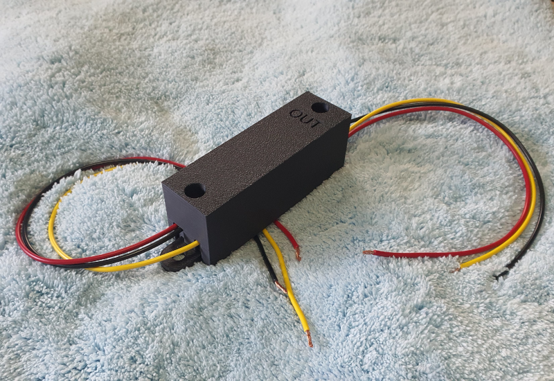
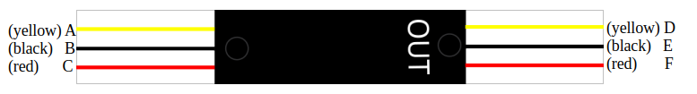
Your delayed power module comes in a black plastic case with mounting lugs on the bottom. The top is marked with the word “OUT” at one end. The wires that come from the unit at this end (D, E, F) are the outputs which should be connected to the I/O hat. The wires A, B and C are the inputs to the relay module.
Note that all references to “12v” refer to the nominal value, and the true voltage will be battery voltage which will vary depending upon whether the engine is running or not. This variation is not an issue.
Key:
- A – Switched 12v (from your vehicle’s ignition). This input is used to trigger the module.
- B – Ground
- C – Permanent 12v (from battery or other permanent source, should be fused).
- D – Ignition pass through to I/O hat
- E – Ground pass through to I/O hat
- F – Switched 12v Output (from the relay) to I/O hat
Make the following connections:
- Connect an ignition key switched +12v source to input A (yellow wire)
- Connect a battery ground to input B (black wire)
- Connect a permanent +12v to input C (red wire) via a fuse
- Connect output D (yellow wire) to the IGN input on the I/O hat.
- Connect output E (black wire) to the Ground power input on the I/O hat.
- Connect output F (red wire) to the +12v main power input on the I/O hat.
In addition to this, you will require the following connections on your I/O hat:
- Either your 3 serial connections (ECU TX, PI TX, ECU GND);
- Or the relevant canbus connections for your implementation.
(you might want both of these depending on what you are setting up)
The permanent +12v input should be fused. 5A is usually sufficient but use your own judgement here.
Operation
When you connect B and C, the module will turn on for around 5 seconds and then turn off again. Once this has occurred, the module will only turn on when the yellow trigger wire (A) receives +12v, and will turn off after a delay when the signal is removed by turning off the ignition.
When +12v is removed from A, the delay module will switch into shutdown mode. This makes it wait for a short period of time before disengaging the power relay. The time it waits for is set to approximately 5 seconds. This is more than enough time for SDC to safely perform its shutdown activities before the power is removed.
If you wish to lengthen the delay time of the relay, this is possible but requires opening of the device in order to do so. Instructions on how to do this can be provided on request.
Testing the delay module in isolation from the rest of the system.
To test the delay module by itself, first make sure that the ends of the D, E, and F wires are all insulated so that they can’t touch each other. Then connect as below:
- Connect battery +12v to C
- Connect battery ground to B
The device will turn on (relay will click), stay on for around 5 seconds, then turn off again (another click). This brief turn on is the module initialising itself when power is first connected.
To test power on triggering, take the A yellow input wire and touch and hold it onto the +12v battery input. This simulates turning on the ignition key. The relay will click once and the device will stay in the ‘on’ mode as long as you hold the wire in place.
To test the delayed shutdown, lift the end of A off the supply. The device will switch into shutdown mode. Count 5 seconds or so. The relay should click again after around 5 seconds.
Software Configuration
To enable controlled shutdown within SDC, you will need to configure an input in the SDC.INI file. From SDC Tools, connect to the device and Press the “Edit ini file…” button. Scroll down the file until you find the section labelled [buttons]. You should find a line that says:
;shutdownbutton=13.pd,shutdown
The semicolon signifies that the line is a comment. Remove the semicolon from the beginning of the line to convert it from a comment to an actual setting, and press OK. The file will be saved back to the device.
You will need to restart the device for the configuration to take effect.
Powering Other Devices
The relay on the shutdown module is rated for 10A but I would not recommend going beyond about 5A. A typical I/O hat / Pi / 7” Screen combination requires up to 2A depending upon the screen. You can therefore use the +12v output from the module (the bottom right connection in the image above) to power other devices in parallel with the hat, but you must have individual voltage regulators in front of each device according to its requirements since the output from the relay module is always the nominal +12v.