Tyre Pressure Monitoring
- Tyre Pressure Monitoring
- TPMS Modes of Operation
- Installation
- Setting up SDC To display TPMS data
What is it?
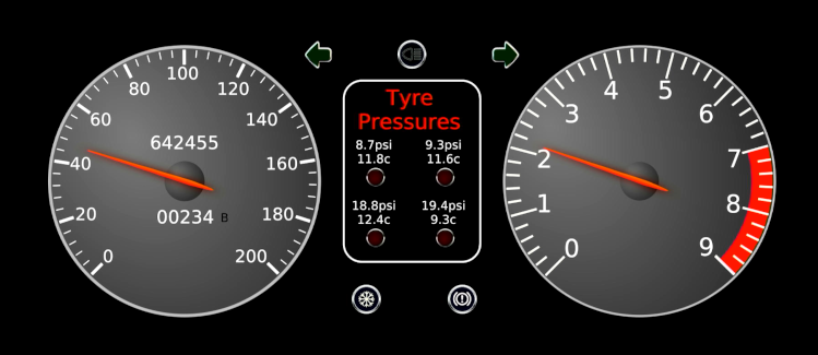
SDC provides standard attributes for reporting the tyre pressures, temperatures, and alarms for up to 4 wheels. The SDC TPMS receiver provides the means to capture tyre data and make it available for display and/or logging within an SDC installation. In order to achieve this, you will require the following:
- A set of Bluetooth LE tyre pressure sensors
- An SDC TPMS receiver
And you may already have or will require:
- An SDC I/O Hat with CANBus inputs
- A Raspberry Pi running SDC with CANBus enabled (requires a license)
Your choice of configuration
Most installations will be fine with just one SDC TPMS receiver servicing all four wheels and connected to the SDC CANBus.
Since Bluetooth LE signals can be variable in strength, depending upon other factors such as what else is operating on the same frequency, it is possible to use multiple SDC TPMS receivers in order to place detection closer to the signal itself (wheel or wheels). You can add any number of receivers in any combination, as long as these rules are followed:
- If you want to use a single TPMS receiver, configure it as a standalone. This device must be connected to the SDC CANBus.
- If you want to run multiple receivers, there must be one and only one SDC TPMS receiver configured as the ‘master’. This device must be connected to the SDC CANBus.
- Optionally, there may be one or more SDC TPMS receivers which are positioned closer to hard to detect wheels, and are either connected to the CANBus as standalone devices, or are configured as a ‘slave’ device (wireless transmission to a master).
You don’t need to make any installation decisions at the time of purchase; all SDC receivers contain the same hardware and can be swapped between configurations at any time.
TPMS Modes of Operation
There are three possible modes of operation for an SDC TPMS Receiver:
- Standalone (BLE receive, CANBus transmit)
- Master (BLE Receive, Wireless receive from Slaves, CANBus Transmit)
- Slave (BLE receive, Wireless transmit to Master)
The receiver supporting these configurations is just one design of hardware, so you can swap between these configurations at any time via an on-device web page configuration tool. The receiver includes the relevant componentry for CANBus transmission, meaning no other hardware is needed for it to communicate with a suitable SDC installation.
Standalone Mode
It is possible to implement TPMS with just one receiver configured as a “Standalone”, connected to the SDC CANBus. This is probably the most common installation. A receiver in this mode would just receive data from all four wheel sensors, and transmit that data over the CANBus for SDC display controllers to read (and datalog where desired).
By spreading the selected wheels across multiple receivers you can add extra standalone’s located closer to the wheel sensors to help with signal strength issues. You can have as many as you like, but it doesn’t make sense to have more than 4 in total for obvious reasons. Each standalone would be connected to the CANBus and would contribute data from the wheel(s) it is enabled for.
Configuration examples:
- You could have one standalone configured for all 4 wheels, connected to the CANBus;
- Or you could have two standalones, one configured for front left and front right, and the other configured for rear left and rear right. Both devices would be connected to the SDC CANBus. You might mount the front one close to the front wheels and the rear close to the rear wheels;
- Alternatively you could have 4 standalones, with each one configured for one wheel, all on the same CANBus, mounted near the four corners of the vehicle.
- It’ll work with three devices too.
- There’s no point in having more than 4 on a vehicle with 4 wheels!
For most vehicles, a single standalone device will be enough provided there is no interference from other devices broadcasting on the Bluetooth frequency. You can of course add secondary devices closer to the relevant wheels if sensor detection is too limited. You do not need to make this decision on initial purchase as secondary devices can be easily added later.
Master Mode
It only makes sense to configure one receiver as a master if it is going to be combined with one or more slave receivers. Really though a master configured to receive BLE data directly for all four wheels is the same as a single standalone as it will not have any slaves sending it data. When configured for all four wheels a Master receiver will read BLE messages directly and put the data directly on the SDC CANBus.
So a Master can detect TPMS data in two ways concurrently:
- BLE messages received directly from TPMS sensors (for the chosen wheels)
- Sensor data received directly (wirelessly) from Slave devices (for the wheels not selected as direct BLE)
The Master must be connected to an SDC CANBus in order to be able to transmit the data it receives from either of these two sources to the SDC software running on your Raspberry Pi, which must also be on the CANBus via an I/O hat of course.
To configure a Master, you can select the wheels you want the master to handle directly, by listening for BLE advertisements, and leave unchecked any wheels you want slave receiver(s) to provide.
Configuration examples:
- One master at the front of the vehicle, enabled for front left and front right wheels. This receiver must be connected to the CANBus. One Slave receiver, configured for the two rear wheels. This device sends its updates wirelessly to the Master using its onboard radio. The slave is not connected to the CANBus.
- One master for the front, two slaves at the rear.
etc.
Slave Mode
A slave receiver is configured for specific wheel(s) and receives data via BLE for those wheels, just as a standalone would. Any BLE data received for wheels not configured will be ignored. When configured as a slave the receiver will wirelessly broadcast the wheel data it accepts to the Master receiver (which must of course also be present somewhere in the vehicle). In other words the slave bridges messages from the TPMS Sensor to the Master receiver.
Using one or more Slave devices with a Master can help in a few ways if needed:
- As slaves transmit their data wirelessly, you can avoid the need to extend the CANBus around the vehicle (assuming there is no interference on the frequency).
- With the wheels being outside the ‘tin box’ of the vehicle, and the TPMS receivers inside it, wireless transmission from slave to master is more likely to work than from wheel to Master, especially if the Master or single standalone is relatively far away from the sensor.
- The Slave uses a much more powerful radio transmission than the BLE signal the sensors use sp you can position the slave closer to the sensor and further away from the Master.
If you try to implement slaves and their broadcast to Master is problematic due to interference, then you can still just change the configuration to standalone and put those slave devices directly on the SDC CANBus.
Sensor Detection
SDC TPMS Receivers record the address of every sensor received which matches those wheels enabled for BLE reception. The addresses are stored in non-volatile memory and retained when power is removed. Once an address for a particular wheel has been stored, any other sensors or slaves broadcasting data with a different address but for the same wheel ID will be ignored.
If, for example, you have two vehicles within range of your receiver each with a different set of sensors on-board, then the addresses are used to determine which sensors to accept and which to reject. During this setup phase where addresses are being detected it is important that other sensors not related to the vehicle being set up are kept out of range or disabled in some way.
On the setup page, there is a place where sensor addresses that have been detected are shown. These addresses can be manually overridden in case you have a situation where the wrong sensor from another vehicle is being detected and you can’t get out of range to avoid it.
Every TPMS receiver has an on-board web page for status information (shows which sensors are being detected and when they were last seen) and an on-board configuration page which enables you to specify the friendly name, pressure limits, mode of operation (master, standalone or slave), CANBus speed (integration with SDC requires 1Mbit), the set of wheels to be detected over BLE (non-selected wheels are ignored or received via slaves), and if necessary to specify specific addresses of the wheel sensors. These pages are accessible as soon as you’ve configured the network details page after initial power-on.
Whether sensor data is coming directly from BLE or via a slave, the sensor address detection works the same way.
Installation
Do not install the TPMS Receivers on the wheels of your car yet. Leave the batteries out of them. You should only do this last step once you have completed configuration. It’s not really a problem if you do but it’s just easier to manage if that is the last thing you do, particularly if you have more than one set of sensors.
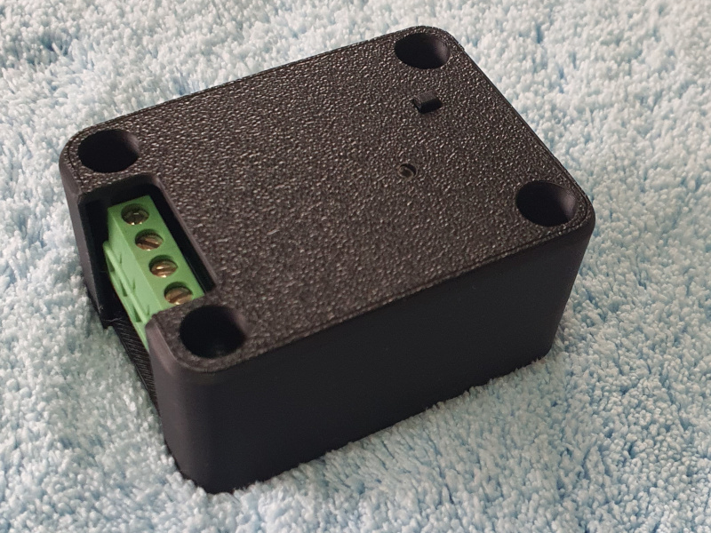
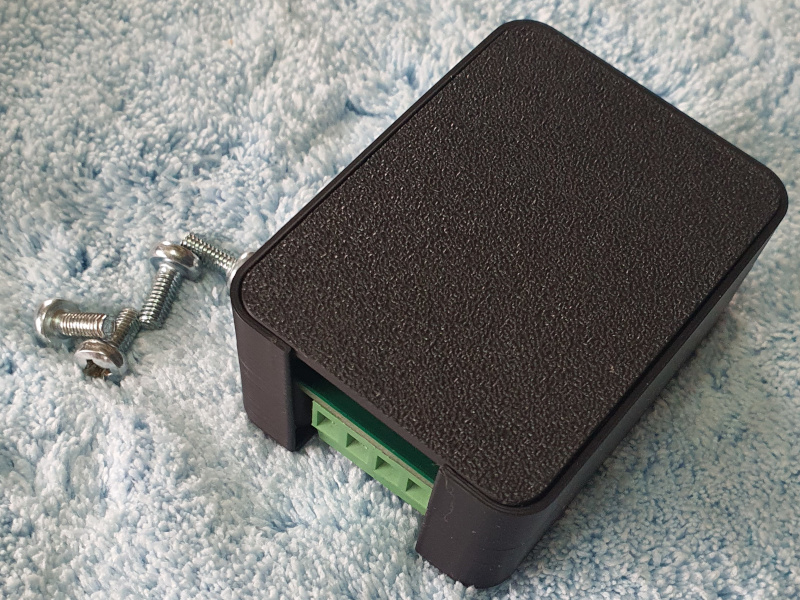
Your TPMS Receiver comes in a small case, and has 4 screw terminals at one end and a USB type C port at the other end.
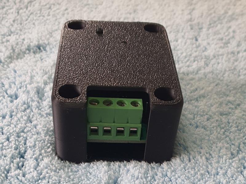
With the screw terminals facing you, from left to right they are:
- Ground
- 12v (nominal) - voltages up to 20v are allowed. Normal alternator voltage is fine.
- CAN High
- CAN Low
The USB port, on the opposite end of the device, is not normally used.
On the top of the receiver are:
- The status LED
- The control button
Connect an ignition fed supply to the first two pins. The receiver boots immediately when power is applied and if this is the first power up it will jump into initial setup (Access Point) mode: white LED short flash at 1hz.
If the receiver has already been configured it will listen for Pressure Sensors that are advertising themselves. If you are within range of the configured network it will connect immediately.
You can connect the receiver to any 12v supply for bench testing and configuration prior to installation. The receiver will power up with input voltages down to about 7v. I usually set my bench supply to 13.5v for testing and let the on-board regulator do the rest.
Step 1 - Connect the receiver to your network
On first power up, or after a hard reset (see later), the receiver boots up in Access Point mode, with an IP address of 192.168.4.1.
The LED will briefly flash in white once per second.
The receiver will show up as a WiFi access point called SDC_TPMSxxxxxxxx where xxxxxxxx are eight hex digits (0-9,A-F).
If you are setting up multiple devices I suggest you power them up and configure them one at a time so you know which is which.
Once the receiver is powered up, use your computer or phone to locate the WiFi network and connect to it. The SSID will be TPMSxxxxxxxx as above, and the password is “password” (without the double quotes).
Once you are connected to it you can point your browser at http://192.168.4.1 and you will be presented with the initial configuration page. All of the pages on the receiver are very simple and will work from a mobile phone.
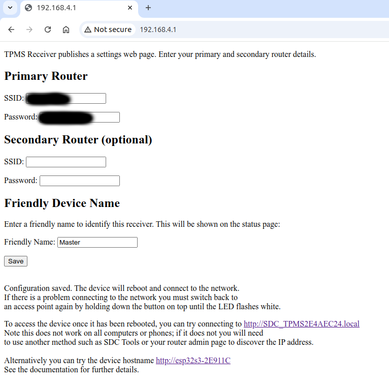
The initial setup page will look something like this:
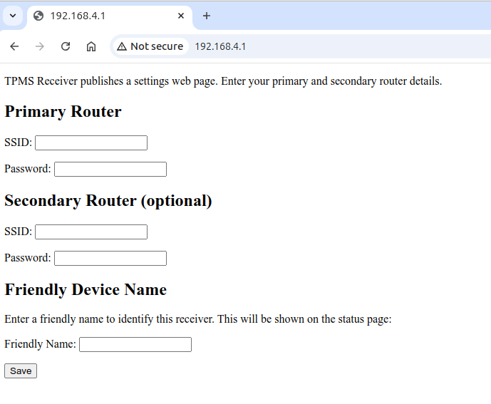
Use the initial configuration page to set the Primary SSID and Passkey of your own WiFi network. Optionally, you can also set up a secondary network. This is explained below.
You can also set a friendly receiver name here as well; this is displayed on the status web page. When you save these settings, the receiver will reboot and attempt to connect to the network you have entered.
On pressing the save button, you should see something like the following:
If the receiver fails to connect to your network, you can reboot it by cycling the power. If it fails after multiple attempts make sure you have it close enough to your router. If even in close proximity it won’t connect then you might have entered the details incorrectly. To re-enter them, you need to hard reset the receiver. This will put it back into access point mode. See below for details on how to do that.
Note that failure to connect is a normal scenario when you are not within range of the configured network (e.g. away from home), and is not considered an error. It does not prevent the receiver from carrying out its configured role; it only prevents you from accessing the management web pages. You do need it for configuration in the first place of course!
Primary and Secondary Networks
The idea behind primary and secondary networks is that you can configure both and the receiver will try to connect to the secondary network if the primary connection fails.
The network connection currently being used is signified by a brief flash of the status LED in orange as detailed below.
Note that the receiver will not continuously try the primary and secondary networks. It tries one first and then the other, and then stops swapping between them. The last network connected to is stored in non-voltaile memory and this network will be tried first the next time the receiver is booted up.
Therefore it will either try Primary first, then secondary, then stay on secondary in case it comes up, or it will try secondary first then primary and stay on primary in case it comes up. If neither network is available, the stored value is not updated.
If you do not put any details in the secondary network connection then only the primary connection will be used. You must always specify a primary connection.
After initial configuration during install, the primary network will be tried first.
While it is running, you can request the receiver to switch between the primary and the secondary networks by doble clicking the button on the top of the receiver.
How should you use this?
Put your home network in the primary, and your phone hotspot in the secondary. Then when you are not at home you can enable your phone hotspot and still be able to manage the receiver configuration (e.g. set the pressure alarm levels).
After a successful network connection
The receiver signifies its network connection status and activity using the colour of the Status LED:
- When the receiver is scanning for TPMS advertisements (pressure data) it sets the status LED to bright blue for 5 seconds
- When the receiver is not scanning for any TPMS advertisements (because no wheels are enabled for BLE) it sets the status LED to bright blue for 2 seconds.
- After the initial 2 or 5 second period, the receiver will briefly flash the status LED orange either once or twice. If it flashes once, the Primary network is being tried (or is connected). If it flashes twice, then that’s the secondary network.
- After the orange flash, the LED goes either dark blue (it is connected to the configured network) or dark green (it is not connected to the configured network).
After the receiver has been configured and connected to your network for the first time, all wheels will be enabled and the receiver will be in standalone mode. This can be changed using the configuration page in the next step. At this point you should connect the phone / tablet / pc or whatever you used for initial configuration back to the same network as the TPMS Receiver, so that you can access the status and application settings pages.
Step 2 - Connect to the receiver’s web page and configure it
After the network is configured, the receiver will be in TPMS Scanning mode and show the status LED as outlined above. It will keep doing this until power is removed. The receiver will operate in terms of detecting sensors and be able to be configured, but you won’t be able to get any TPMS data onto an SDC display until you connect at least one TPMS device to the SDC CANBus.
With the receiver connected to your network, you can access its main page using the IP Address your router has assigned to it. There are several ways you can find this address:
- You can try the links reported on the initial configuration page after you press the “Save” button. There are two links: The first is an mDNS link, which is the one with “.local” on the end, and the second is the true hostname of the processor inside the receiver. Sometimes neither of these will work - it depends on what the computer system you are using supports. If this is the case, you need to use the IP address via one of the other methods below.
-
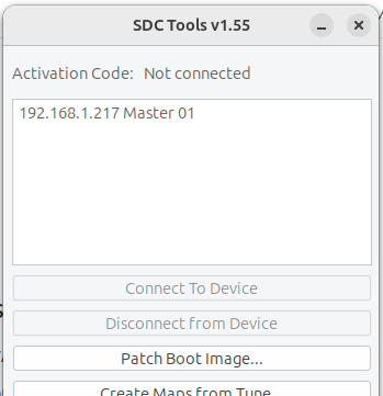
Run SDC Tools and wait for it to detect the receiver. SDC Tools will not let you connect to the receiver as it isn’t an SDC instance (it will report a protocol version error if you try), but it will show you the IP address in the receiver list. The friendly name you entered at initial configuration will show up in the SDC device list.
You should see something like this. The friendly name has been set to Master here, and the IP address shown is the one you would use to access the status and settings pages in your browser:
- Alternatively, you can connect to the administration pages of your router and find the receiver there.
When you are not within range of your router, the receiver will just not have any network connection but will continue to operate in whatever mode you have it configured in. If you intend to change the receiver configuration when not at home I recommend you configure it with a router that you will have available such as the mobile hotspot on your phone.
Worst case, if you need to change the network connection from the one you chose because you are not near that network, you can hard reset the receiver to go back to access point mode and access the initial configuration page via http://192.168.4.1. This deletes the detected device addresses from non-volatile storage, but they are easily detected again (just make sure there aren’t more than one set within range).
Once you know the IP address and/or hostname of the receiver, you can connect to it over your network from a browser by entering:
http://<ip address>
e.g.
http://192.168.1.217
or
http://esp32s3-2e911c
You should see a page that looks something like this:
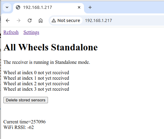
The messages about the 4 wheels will be different dependng upon how you have configured it. Here, the receiver is configured as a standalone waiting for BLE messages for all four wheels (the default configuration). The friendly name was set to “All Wheels”. The page will automatically refresh every 30 seconds.
A reminder that if you are configuring multiple devices, at this early stage you should probably just have one powered up at a time until you know which one is which from an IP address perspective.
Step 3 - Configure the receiver instance for the operating mode you need
Most people will be running a single receiver in Standalone mode. This mode senses data from all four pressure sensors directly via BLE and places the data directly onto the SDC CANBus. It is the default mode after initial configuration. As a result, you may not need to change some of the settings.
- Maximum and minimum front and rear pressures
These pressures are used to determine the alarm flags (see alarms section further down this page) - CANBus Speed
This is left at 1Mbit for SDC. The other supported, slower, speeds are listed and may be used if you are integrating the receiver into some other system. - Operating Mode
Defines which of the operating modes to use: Master, Standalone, or Slave. - Enable/Disable Direct BLE Sensing
There is a tick box for each wheel. A check in the box means that the receiver will try to sense BLE data directly for the wheel. If unchecked, the expectation is that data will be delivered from a different receiver: Either another standalone device connected to the CANBus, or a slave sending data to this device, where this device is configured in Master mode. For slaves, you are setting which wheel(s) the slave will gather data for and transmit to the Master. For the Master, you are setting which wheel(s) (if any) will be monitored directly via BLE. And the same for standalone mode. - Wheel Address override
These boxes each support a 2 digit hex number. The three boxes on each row represent the address for a given sensor. The sensor addresses are populated from received BLE data. You may override the received sensor addresses with different ones if there is more than one set in the vicinity and the receiver picks up the wrong one(s).
Press Save to save any changes. If you change the operating mode, the receiver will reboot. If you alter the BLE sensing checkboxes, all receiver data will be cleared and you will need to wait for refreshes either from slaves or from the sensors themselves (depending upon the mode the receiver is in).
Hard Reset / Reconfiguring the network
If you type the SSID or Passphrase incorrectly then you must reset the receiver back to access point mode in order to reconfigure it. To do this, there is a small button on the top of the case, just opposite the LED. Hold down the button for around 6 seconds and it will perform a hard reset and go back into access point mode. The status LED will first show bright red, then short-flash in white once per second. When it is short flashing white, it is in access point mode and the reset has occurred.
When a hard reset is done the following changes will occur:
- Stored sensor addresses will be erased
- The network configuration is erased so that the next boot results in access point mode
- The minimum and maximum pressure settings are erased
- The CANBus speed is set to 1mbit (this is the speed required for SDC anyway)
- All four wheels will be enabled for BLE
- The operating mode is set to Standalone
- The friendly name is erased
CANBus Termination
As you are no doubt aware, a CANBus needs to be terminated on each end in order to ensure that the communication works properly. The normal method for doing this in SDC (with SDC I/O hats) is to enable the CANBus termination resistor that is present on the PCB by placing a jumper connector over the relevant jumper pins.
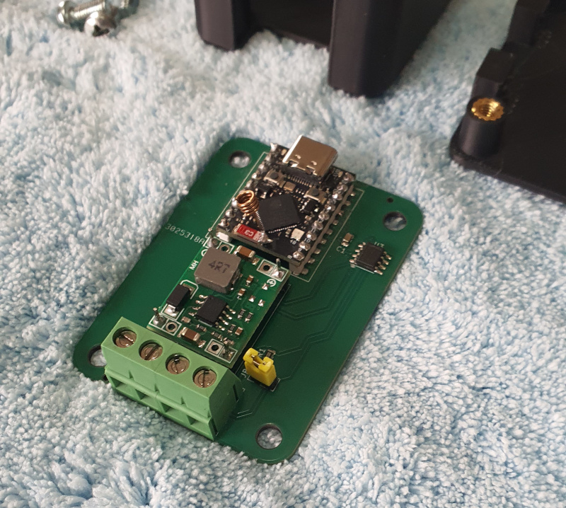
The SDC TPMS Receiver also contains an optional termination resistor. To enable it you need to remove the cover from the case:
- Disconnect all cables from the screw terminals
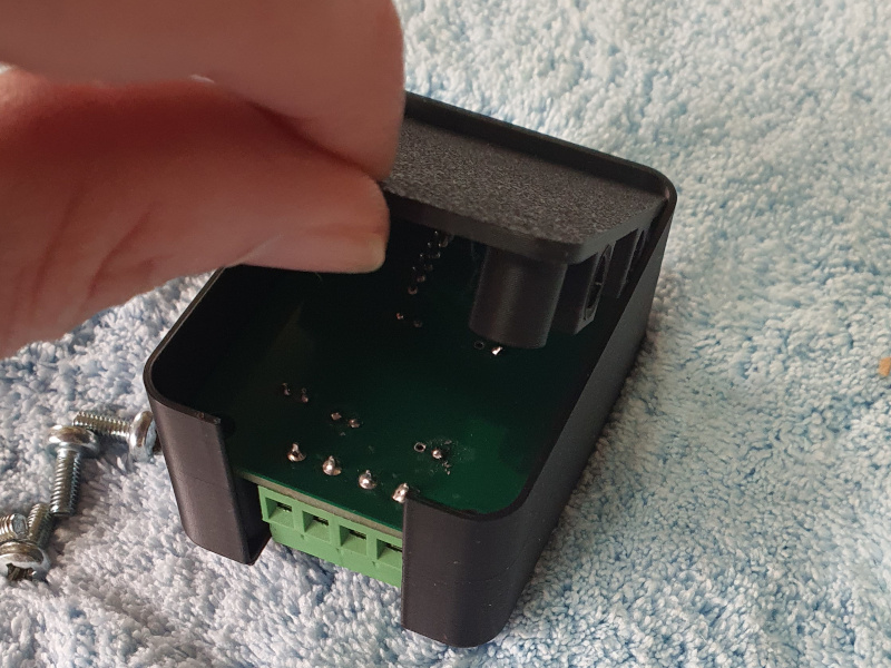
- Remove the 4 screws from the corners of the case. They are not done up tightly; just enough to hold in place.
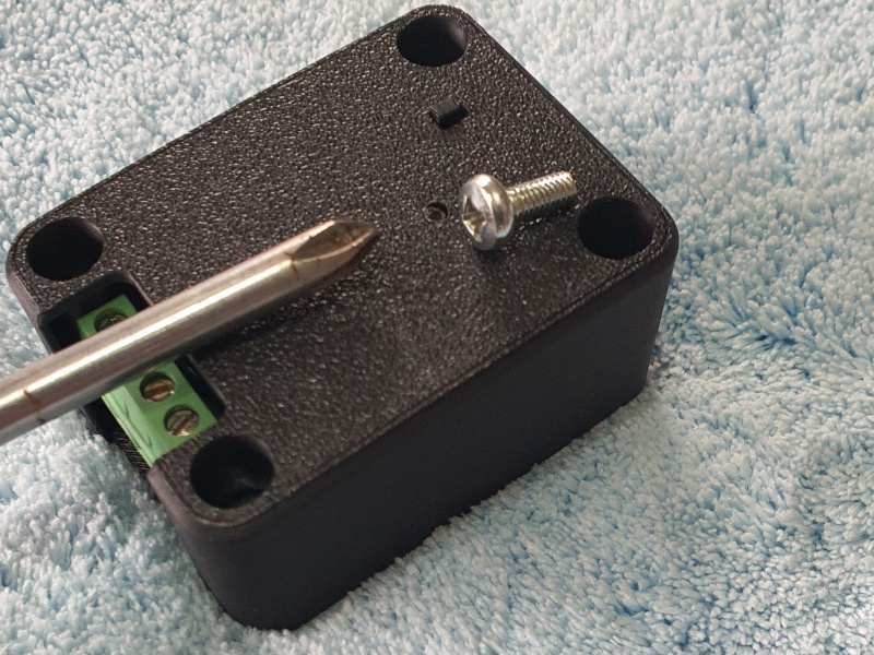
- Turn the receiver upside down and lift the base upwards away from the cover. This will leave the cover and the now upside down pcb together.
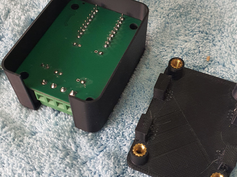
-
The PCB inside will be loose, since the outer screws that you removed are what hold it in place. It can now just be lifted out by carefully taking hold of the screw terminals and lifting.
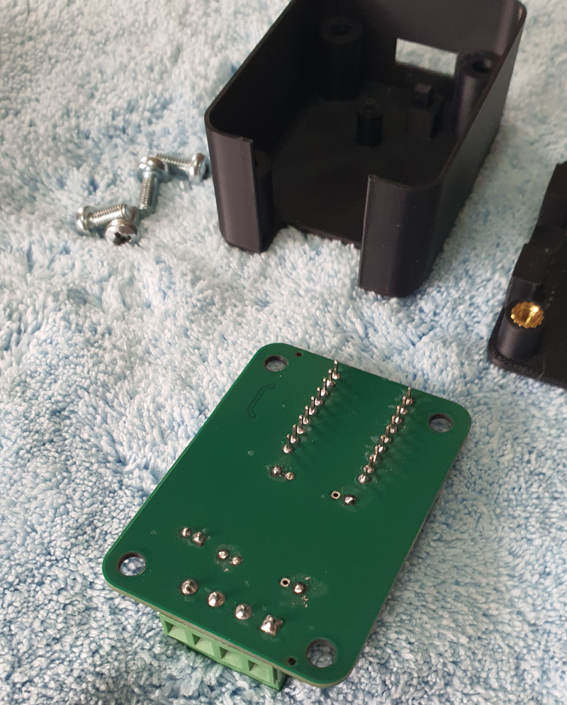
-
Turn the PCB over. Next to the screw terminals there is a 2 pin header, with a jumper already attached to just one pin (yellow in the image, but it might be a different colour in your device).
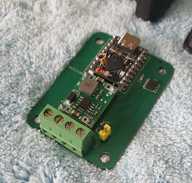
-
Move the jumper connector so that it is connected to both pins. This closes the jumper and enables the termination resistor.
- Turn the PCB upside down again and place it inside the cover as it was before. Make sure the screw terminals are at the end that has a large opening.
- Put the base in on top of the PCB. The base is symmetrical so it fits either way around.
- Hold the parts together with your fingers, turn everything the right way up and reinsert the screws in the corners.
- Turn the screws until they are snugged up. Do not overtighten to avoid damaging the housing.
If the receiver is not at the end of a CANBus, you do not need to terminate it. Also if you move it from the end to the middle of a bus, you must remove the termination jumper if you had previously enabled it. Comms over the whole bus (not just TPMS) will fail or at least be unreliable if it is not correctly set.
When installing in the middle of a bus, you can daisy chain the CAN High and CAN Low wires by connecting 2 wires to each terminal. i.e. On the CAN High terminal there would be one CAN High wire input from the previous device, and another CAN High wire output which goes to the next device. And the same for CAN Low.
Do not be tempted to run a 2 wire spur from another CAN device; this is not a valid wiring scenario for CANBus and won’t work. It must be a daisy chain of devices.
Setting up SDC To display TPMS data
Once you’ve got a working TPMS Receiver (or network of receivers) you will need to configure SDC to display the data from the wheel sensors. There are some prerequisites for getting tyre data into SDC:
- One or more SDC TPMS Receivers
- An SDC CANBus implementation
- One or more SDC devices on the CANBus in addition to the Receiver (this can include a TinySDC)
Remember that a CANBus always requires at least 2 devices, so one can be the TPMS receiver and the other can be the Pi used for an SDC Display with an I/O hat containing CANBus support. You will of course also need a CANBus license for the SDC instance.
Attribute Names
SDC Provides the following attributes for each wheel:
- Pressure
- Temperature
- Alarm flags
- Battery Percentage
These will be populated by the TPMS Receiver using the data it gets from the sensors. Each of these 4 values is stored on a per wheel basis, meaning that there are in total 16 values transmitted and stored in SDC. The attributes you use (in the same way that you might use, say, “rpm” on a ValueGauge) have the following naming convention:
<wheel><attribute>
where <wheel> can be:
- fl - front left
- fr - front right
- rl - rear left
- rr - rear right
and <attribute> can be
- pressure
- temp
- alarm
- battery
Examples:
frpressureis the attribute for the front right pressure.rlalarmis the attribute for the rear left tyre alarm.frtempis the attribute for the front right temperature.
Both Pressures and Temperatures are stored multiplied by 100 so that decimal places can be represented. Therefore you will need to use the ‘divideby’ ValueGauge property with a value of 100 to get a correctly displayed temperature. And if you want the two decimal places, then change DecimalPlaces from 0 to 2.
Alarms
The alarms attributes are actually bitmaps. They are defined as follows:
- Bit 0 - Sensor alarm (bitvalue 1)
- Bit 1 - Low pressure alarm (bitvalue 2)
- Bit 2 - High pressure alarm (bitvalue 4)
The sensor alarm comes directly from the sensor. It has an undefined set of heuristics for when this alarm is generated and can mostly be ignored, although it may be useful at some point in the future. The low and high pressure alarms are generated based on the TPMS Receiver settings for front and rear minimum and maximim pressures.
To access these bits, you need to use a boolean gauge and configure the BitValue property. As these alarms are bitmaps this means that more than one bit could be set at once, or conversely you might want one Boolean Gauge to react to more than one bit in this bitmap.
For example, if you want a warning light to flash when the front left tyre is either above or below the maximum or minimum pressure, then you should define a Boolean Gauge with the following:
Attribute flpressure
BitValue 6
The BitValue is calculated to be 6 by adding together the values for bit 1 and bit 2 (2+4). If you wanted to also include the sensor alarm then you could use 7 instead of 6.
For further details on BooleanGauges please see the BooleanGauge documentation.
Alarms are generated based on the settings in the TPMS Receiver. In a master-slave configuration, only the minimum and maximum pressures in the settings of the master are used to set the alarm bits. Any slave settings are retained in the slave but ignored.
In a standalone case, each TPMS Receiver controls the alarms for the wheels it is managing and puts that data directly onto the CANBus.
If you have a single master with no slaves, this is the same as a standalone (and you should just change the setting to standalone).
A single standalone receiver monitoring all 4 sensors is the most common and simplest implementation, and here the alarms apply to all 4 wheels via the settings in the standalone.