Getting Started with SDC Pro 7
Support
If you need help, please contact me using the e-mail address you received messages from when placing your order. I have not published the address here in order to avoid spam.
About your software license
The software license on the Pro 7 is a ‘full’ license. It is enabled for 255 pages with all extra features enabled so that it is somewhat future-proof. Please note that some of those extra features require hardware that is not part of the Pro 7 or may require ports that are not available or are being used for other purposes. There is only one USB port on the Pro 7 for example, and it is used for the touch screen.
Your license is perpetual and entitles you to all future software releases of the SDC product and its tools.
The license is tied to the Raspberry Pi that came with this Pro 7, and is registered to the name you placed your order under. The Pro 7 is pre-registered in your name so although you will be sent your license details by e-mail you do not need to apply them to it.
A record of your license is kept by us as well as being e-mailed to you, but please keep a copy of it in case anything happens with the SD card and you want to reinstall the software.
For help with the software, see the other sections on this website.
Power and Data Connections
Where used, screw terminals need to be tightened properly to prevent them from coming undone. The green terminals supplied with the Pro 7 are good quality but it is good practice to hold the screw terminal with your fingers when tightening to reduce the torque through the solder connections underneath.
It is also good practice to ensure that cables are clamped with some slack before they enter the device, to reduce the chances of them being pulled out of the terminals.
Step 1 - Connect the serial or CAN cables from your ECU
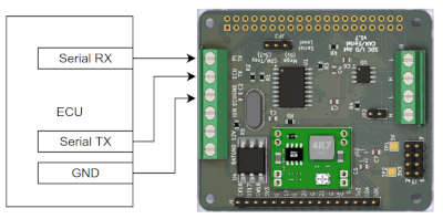
The back of your Pro 7 may look slightly different to the image below, but the connection points will be in the same place.
Speeduino Serial
Secondary Serial is a speeduino specific solution. You can’t use it for any other ECU.
- Connect a Ground from your ECU to the ECU GND screw terminal on the back of the device.
- Connect the ECU’s Secondary Serial TX pin to the input labelled ECU TX on the back of the device.
- Connect the ECU’s Secondary Serial RX pin to the output labelled PI TX on the back of the device.
- Make sure you set the Serial voltage jumper JP3 correctly. It comes shipped configured for 5v serial (Arduino Mega) but if you have an STM32 or Teensy device, which is 3.3v, you will need to move the jumper to the correct position.
The secondary serial port you should be using is ECU specific. On an Arduino Mega running the standard Speeduino firmware, the secondary serial port is Serial 3 and you can access the right pins on a standard speeduino board by soldering to the underside of the Arduino.
For other ECUs and firmware combinations you will need to determine which are the correct pins yourself. On a DropBear ECU for example there is usually a breakout for the serial port inside the case (referred to as the bluetooth header). On some STM32 boards (those running standard firmware in particular) the secondary serial device is Serial2, but the physical connection points are again hardware specific. Sometimes it may be Serial1.
If in doubt, contact your ECU manufacturer and ask them how to connect to the secondary serial port on their ECU in order to determine the correct pins and physical location on the board.
Never connect a 5v serial device to the Pro 7 unless the jumper is in the Mega position.
Canbus
If you have an ECU or other data source that can provide canbus data which SDC understands (including other SDC devices, or an ECU with an appropriate DBC file), or you have SDC or other devices you want to send CANBus data to, then:
- Connect the CAN High of your CANBus to one of the CANH inputs on the right hand side of the board (the opposite side to the serial connections)
- Connect the CAN Low of your CANBUS to one of the CANL inputs on the right hand side of the board
- Make sure all that are connected together are using a common ground connection.
Check the rules for CANBus termination and enable the termination resistor on the board if it is needed (JP2). Make sure you daisy chain your CANBus connections. Do not introduce a spur or implement some sort of star configuration as this WON’T work.
Step 2 - Connect the Power supply to the device
You must make sure that your ECU receives power at the same time as or before SDC when the ignition key is turned on, so that when SDC boots it can receive data from your ECU.
The Pro 7 is shipped with a delayed shutdown module in a separate case with fly leads on both the input and the output sides. This provides a clean shutdown process when the ignition is turned off. This module requires both permanent and 12v switched power.
There are 3 cables to connect from the module to the back of the Pro 7. See the Delayed Shutdown Module instructions for full details. Make sure the cables you connect are from the “OUT” side of the module.
Once you have the delayed shutdown module connected, the Pro 7 will boot whenever +12v is connected to the yellow input wire (via the ignition key in an actual installation). The device will shut down when that voltage is removed by turning off the ignition. When the ignition is turned off, you should see the boot screen for around 5 seconds, then power will be removed and the screen will go off. When the power goes off you will hear the power relay click.
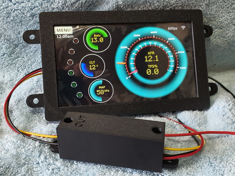
After booting, you should see a WiFi icon appear in the top right of the screen on the demo pageset once a connection to your network is established. This will take a few seconds after boot. If it does not appear, then check your network connection details are correct or follow the troubleshooting section. Note that the WIFI icon is just a connection indicator – it does not show the strength of the signal.
When you turn off the ignition the device will immediately go into shutdown mode, where removal of power is delayed by around 5 seconds to allow system data to be saved. If you turn the ignition back on before this delay period expires, the delay will be cancelled and the device will stay powered. This leaves the software terminated but the device powered up until you turn off the key again (at which point the delay restarts). If at this point you want to keep the ignition on and have the software running again, simply touch the screen and SDC will reboot.
Step 3 - Configure the WIFI connection
To configure the WIFI you will need to remove the SD card from the Pro 7. Before you remove it take note of how far into the card slot it is inserted and the orientation of the contacts so you are clear what it looks like when it is inserted properly.
Make sure the Pro 7 is fully shut down before removing the SD card.
With the face of the screen resting on a towel on your work surface, the unbranded, black, side of the SD card with the contacts on it will be facing upwards.
The SD card is located on the edge of the Raspberry Pi, at the side where the power and serial connections are made on the I/O hat. You should see a tail of transparent yellow tape sticking out. Pull horizontally on that tape to remove the card.
After removing the card, insert it into your PC and follow the instructions for setting up the wireless network at this page about WIFI Setup
Finally, safely eject the card from your PC and reinsert into the Pro 7 before moving onto the next step. Be sure to push it fully home with your fingers but if any more than gentle force is required, make sure it is straight and the correct way up.
Step 4 - Install the SDC Tools
Download the tools at the downloads page here
Install the tools binary and run it. x86 Linux and Windows are supported only. On windows you may have to acknowledge execution of an unsigned application.
Once the tools have started, wait for your device to appear in the list, and then you can use the connect button to connect to it. Check out the help pages for further details of how to use the tools.
The device is configured to start in demo mode. This plays back a recording of data so that you can see the device working. Follow the instructions at the first time boot section to change it from playback to serial so that you can see data from your ECU.
Troubleshooting
Network connections
If you have problems getting the device connected to your network, then check the following:
- put the device as close to your router as possible, to ensure a strong signal, and reboot it.
- try a different network if you can. For example, most mobile phones offer a hotspot capability you can use. You will need to connect both your PC and the device to the hotspot.
- try limiting the wifi to the 2.4ghz frequency (by using the instructions in this section) as this has a longer range and is typically more solid connection wise.
- if you are still stuck, then try the alternative network connection method on the SDC help pages at the bottom of the page in the getting started wifi section
No data is being received after switching to serial mode for Speeduino
- Check your serial connections are the correct way around. Mega TX to SDC “ECU TX”; Mega RX to “PI TX”. If you are unsure whether you have them the right way around, it is safe to swap them over to test.
The mega pins you are using must be for Serial 3. They are labelled TX3 and RX3 on the Arduino pinout diagram. You won’t be able to see markings on the board as it is upside down when attached to a speeduino board, so make sure you have taken into account the fact that the pins are are on the opposite side to the arduino pinout once the board is upside down. Some Speeduino boards break out the serial pins onto a separate header; check your board’s documentation for details.
- Check that you have a ground connected between the two; without it the serial voltages maybe be offset, causing communication errors.
Non 5v serial Speeduino devices (STM32 and Teensy)
If you switch to a device that uses 3.3v instead of 5v for serial data then you must make sure you move the JP3 jumper from the Mega position to the STM32/Teensy position.