Introduction
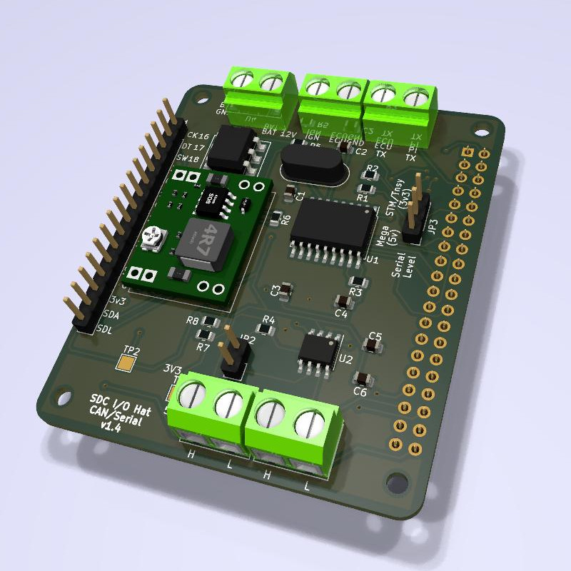
The SDC I/O hat is used to provide data and power to your Raspberry Pi, normally in conjunction with a delayed shutdown module. It contains an on-board voltage regulator which is set to 5v, together with an ignition sense input to provide a signal to the Raspberry Pi that shutdown is required. It also contains connections for Speeduino Serial Input and CANBus I/O which can be used concurrently.

Connections
You must set JP3 properly before enabling the speeduino serial connections. Set the jumper to the Arduino side for any 5v serial speeduino (e.g. Arduino Mega). This is the Arduino pin connected to the middle pin with the jumper. Set to the STM32/Teensy side for 3.3v serial devices. This is the STM32/Teensy pin connected to the middle pin. Getting this wrong may damage the serial port on your Raspberry Pi. You cannot use this connection method for non-Speeduino ECUs.
If you are using a delayed shutdown module, you must connect the power and ignition trigger wires from the module to the I/O hat, and connect the permanent power and trigger wires to the module. For details on how to do this, follow the delayed shutdown module guide.
If you are not using a delayed shutdown module:
- Connect a permanent battery ground to the “BAT GND” input
- Connect a switched +12v to the “BAT 12V” input (i.e. switched via the ignition key).
- Leave the IGN input disconnected
- Do not enable data logging in SDC.
And in both cases you must also (if this SDC I/O Hat is taking data from Speeduino Serial):
- Connect a ground from the microcontroller to the “ECUGND” input.
- Connect the microcontroller’s secondary serial TX pin to the input labelled ECU TX.
- Connect the microcontroller’s secondary serial RX pin to the output labelled PI TX.
If this I/O Hat is taking data from CANBus due to you already having a device taking data from Speeduino Serial and using CANBus rebroadcast, or some other CANBus source, then you must connect the CANH and CANL connections to your existing CANBus. Be sure to enable the termination resistor if it is needed (JP2). It comes disabled by default; the jumper is only connected to one of the pins.
You may also need to specify bus speed and other CANBus related settings in your SDC configuration. See the SDC documentation for further details at https://sdc.v8creations.com
You can connect both CANBus and Speeduino Serial if you want to rebroadcast serial data to other SDC CANBus nodes, or use CANBus auxiliary input for accessories such as indicators, handbrake etc. or other sources of data. For non-speeduino CANBus ECUs, you can’t use (and don’t need) the serial input and rebroadcast capability.
Make sure you have fuses in the +12v circuit somewhere. Location is dependent upon whether you have a delayed shutdown module in the circuit or not.
Speeduino Serial Configuration
Your I/O hat is provided with a jumper to select the serial voltage. By default it is set for a 5v serial device (typically Arduino Mega). This stops any 5v serial from reaching the Raspberry Pi, which is only tolerant to 3.3v.
If you are using an STM32 or other 3.3v device then you must change the configuration. Move the jumper from the Arduino side to the STM32 side (so the STM/Teensy pin is connected to the middle pin). This connects the TX pin from the microcontroller on your Speeduino board directly to the RX pin on your Raspberry Pi so be sure your serial is 3.3v first.
If in any doubt, keep it on the Arduino setting as this will reduce the TX voltage coming from the microcontroller on your Speeduino board. If you have serial voltages that are not either 3.3v or 5v, then you will need to use an external level shifter.
Powering Other Devices
If you have other devices that require power from your 12v system, it is recommended that you use separate regulators which are connected to the +12v output of the delayed shutdown module, rather than trying to tap power from the 5v regulator on the SDC I/O hat. See the delayed shutdown module instructions for further details.
CANBus Connections
Your I/O hat is supplied with a 16mhz crystal which is used as the clock for the CANBus chip. In order to successfully connect this device to an existing CANBus using SDC, you MUST set the configuration of the crystal in the [canbus] section of the SDC ini file:
[canbus]
externalcrystal=16
Do not delete the other entries in the [canbus] section; just change this one from 8 to 16.
Starting with Version 1.70, SDC will auto-detect the crystal speed provided the I/O hat being used is at least version 1.7. In this case the above setting is ignored.
You will find a pair of CANBus connections on the opposite end of the board to the power and serial connections. There are two ports each with a CANH and CANL connection allowing you to daisy chain devices.
If the device is on the end of the CANBus, then there is a 120ohm termination resistor already on the board which you can enable using the 2 pin header. To enable the resistor, place a jumper on the 2 pin header so that the two pins are connected. It is shipped in the open state i.e. termination resistor disabled.
Be sure to follow the rules on CANBus termination resistors. Not enough, too many, or wrong location on the bus will result in poor or no communication on the bus.

Connections
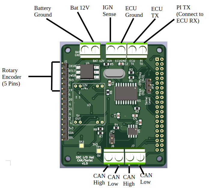
Top connections (left to right):
- Ground
- +12v
- Ignition +12v (when key is on)
- ECU ground
- ECU Tx (input to Hat from Speeuino ECU)
- Pi Tx (output from Hat to Speeduino ECU)
Bottom Connections:
- Jumper for 120ohm Canbus termination resistor
- CAN Hi
- CAN Lo
- CAN Hi
- CAN Lo
2 sets of can lines allow the bus to be easily passed on to the next device.
Left hand row of pins (top to bottom):
- GPIO16 (CK)
- GPIO17 (DT)
- GPIO18 (SW)
- 3v3
- GND (The above 5 pins are the defaults be used for a rotary encoder if you wish to connect one)
- GPIO19
- GND
- GPIO20
- GND
- GPIO21
- GND
- 5V
- GND
- 3V3
- SDA
- SDL (Above pins can be used to connect an I2C RTC)
There is also a jumper on the right side of the board which controls whether the serial is 5v (Arduino) or 3.3v (STM32 or Teensy).
Latest versions have a set of 7 pins for connecting a TinySDC at the bottom right. See the TinySDC page for further details.